Preserving the quality of stored grains such as barley, hops, wheat, corn and other crops has challenged farmers and food processors for millennia.
Today’s modern large grain storage facilities operated by companies around the world depend on technologically advanced fumigation systems that use various fumigating agents, which include chemicals with volatile organic compounds (VOCs) that keep insect and other pest damage low while maintaining the high quality of the stored grain product.
The preservation of stored grain products is a potentially hazardous process involving toxic gases, which must be managed and monitored to protect employees, facility equipment and the environment.
Avoiding the over-consumption of costly fumigant agents is important because residual gas poses a potential air pollution issue and climate threat.
A leading international agribusiness company in the Asia-Pacific region, as part of its export business, needed to meet export requirements that its stored products were free of pests prior to shipment of the grain to international customers and that its fumigation process complied with the local environmental regulations.
The fumigation system’s gas venting levels needed to comply with local requirements for volatile organic compounds (VOC) as measured by a continuous emissions monitoring system (CEMS).
The problem
As part of its commitment to plant safety and health at its facilities, the company recently contacted Fluid Components International (FCI) when it decided to upgrade its silo fumigation system.
This grain storage silo facility is located in an industrial port zone with convenient access to nearby grain farming agricultural regions and a major metropolitan city.
The plant’s engineers needed to measure more accurately and consistently the amount of residual methyl bromide fumigant that is released into the air after the silo fumigation process is complete. Fumigation of the grain products in the silos is required before the grain can be shipped for export. Any leftover fumigant in the silos and pipes is measured and recorded before it is released safely into the atmosphere.
Methyl bromide is an odorless, colorless gas that is widely applied in agriculture to control a wide variety of pests including rodents. While highly effective as a fumigant at the point of use in confined spaces such as silos, its toxicity rapidly dissipates into the air after use and becomes harmless. Classified as a VOC gas, however, the release of methyl bromide gas into the atmosphere is regulated by the local government to protect the environment from the effects of global warming.
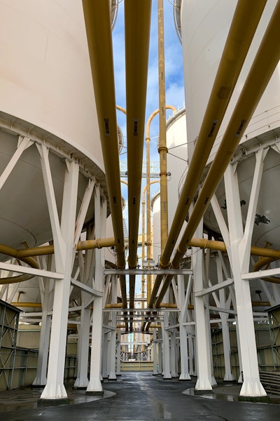
At the storage facility, there are several dozen silos with a single master fumigation system connected by a network of pipes. The fumigant is introduced into the plant’s silos at the base of each silo and recirculated for a specific period before release to the atmosphere when the fumigation process is complete. Monitoring the residual gas to meet the government regulations requires the use of CEMS equipment, which relies on accurate gas flow measurement in multiple locations to provide full and complete compliance data.
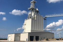
The fumigation system for the silos consists of a central fumigant storage house (left) that delivers by pipeline the flow of the fumigant to the bottom of each silo. The fumigant is then captured at the top of each silo and recirculated. The residual gas from this process is then measured and released up a stack to the atmosphere.
The solution
After reviewing the silo fumigation system and the flow discharge CEMS reporting requirements, the applications group at FCI recommended the company’s MT100 Series Multipoint Thermal Flow Meter (right). This meter combines advanced electronics with multiple precision flow sensors to provide direct mass flow measurement of gases or air for precise, repeatable measurement with low maintenance.
These thermal dispersion meters come with two to eight flow rate sensing points, which is ideal for the complex network of fumigation piping serving the silos. The multiple sensors can be inserted at various depths within a pipe or duct and their outputs are multiplexed (averaged) to measure the flow rate within the process. The flow sensors can be installed either across a mast or can be inserted at multiple points around the process line in a single plane
The plant’s engineers chose the optional CEMS with Continuous Emissions Remote Monitoring System (CERMS) applications package, which meets the U.S. Environmental Protection Agency’s (EPA) 40 CFR Part 60 and 40 CFR Part 75. This package provides a 24-hour interval automated calibration drift test of low and high span points, and interference sensor check.
The CEMS package includes both an automated or an on-demand system self-check of calibration drift (CD) and sensor interference/blockage. The results of the CEMS tests are presented as a simple pass or fail message on the LCD readout and in the DCS. The CEMS option also includes two relay outputs for connection to external devices, one to signal test in progress and the other to signal a fail-test mode.
The plant team was pleased to learn that these multipoint meters will measure flow rates over a wide range from 0.25 to 1000 SFPS (0,07 to 305 NMPS) with 100:1 turndown and with excellent accuracy of ± 0.75% of reading, ± 0.5% of full scale. They are also dual-function and can provide temperature measurement capability from -50 to 850°F (-45 to 454°C), with accuracy of ± 2°F (± 1,1°C).
With their port facility’s rugged coastal outdoor environment, the plant engineers found this meter’s transmitter to be both full-featured and rugged. It featured a choice of output options to interface with virtually any DCS, PLC, SCADA, or recorder. Dual, isolated, high resolution 4-20mA outputs compliant with Namur NE43, HART (Fieldcomm Group™ certified), Modbus, 0-1kHz frequency/pulse and a USB port are all included, standard. Optionally available are Foundation Fieldbus and Profibus-PA bus communications.
For local readings by technicians, the meter’s standard large color touch-screen LCD readout display provides technicians with comprehensive process information showing both analog and digital displays of flow rate, temperature and totalized flow; a user time-base selectable strip-chart of flow rate and sensor status diagnostics. The transmitter’s enclosure is corrosion resistant stainless steel and carries a NEMA 4X/IP64 rating.
The meter’s electronics also include a user programmable data logger feature to which flow rate, temperature and totalized flow as well as fault codes can be recorded on a removable, 8GB microSD card. The instrument’s calibration drift check feature can be initiated on user demand or programmed to run automatically. Results of the test are provided with simple pass and fail messages presented to the operator on the LCD readout display, and, if run automatically, the results are recorded to the on-board data logger.
The plant team installed six multipoint flow meters on the fumigant system where the residual fumigant is released to the atmosphere. The flow sensors were placed in the pipes where the residual fumigant exits into the atmosphere. The transmitters are conveniently located at ground level for ease of direct monitoring by technicians.
Thermal dispersion technology
This multipoint flow meter is designed with thermal dispersion sensing technology, which provides direct mass flow measurement. This technology places two thermowell protected platinum RTD temperature sensors in the process stream.
One RTD is heated while the other senses the actual process temperature. The temperature difference between these sensors generates a voltage output, which is proportional to the media cooling affect and can be used to measure the gas mass flow rate without the need for additional pressure or temperature transmitters.
With its direct mass flow sensor technology, the multipoint thermal meter chosen by the silo storage plant team also includes built-in real-time temperature compensation. This capability ensures repeatable and reliable measurement even in applications where wide process temperature variations are present, such as large refineries in continuous operation throughout the year.
With no moving parts or orifices to plug or foul, this multipoint thermal mass flow meter is immune to dust and dirt. This trouble-free sensing technology with its rugged packaging results in a virtually maintenance free instrument, which delivers continuous operation and at a lower installed cost over an exceptionally long life with low lifecycle costs too.
Conclusions
The six multipoint thermal mass flow meters have been in operation at the gain storage facility for over six months with no incidents. The CEMS/CERMS data reporting provides the necessary documentation required by the regulatory authorities. A seventh multipoint thermal meter has been installed at another storage facility. The company’s engineering teams are considering this meter’s use at other facilities with similar flow measurement applications.